This is a home-made project I was longing to do. I started a bit more than a year ago, playing around with servos, controllers, breadboards and other electronics. I’m amazed I haven’t (yet) burned anything, including myself 🙂 Anyway, here is how to build this Raspberry Pi driven robot or simplified rover.
Material
Here is all you’ll need. I purchased most from cytron.io and a bit from lazada.co.th (note some product could be temporarily out of stock or even discontinued):
- 1x 2-wheel car chassis
- 1x L298N motor driver
- 2x TT Motors
- Some male-to-female and male-to-male jumper wiring
- 8x PCB stand
- 2x Servos for the head rotations
- 1x 8 channel servo controller
- 1x Logic level converter
- 1x 18650 battery holder
- 1x Raspberry Pi HAT UPS (discontinued as of October 2020). Original product here.
- 4x 18650 Rechargeable lithium Li-ion Battery (I got the 6800 mAh ones)
- 1x Aluminum Robotic Claw Brackets For MG995
- 1x Raspberry Pi (I used a 3B)
- 1x Skull head (choose what you want 🙂 )
Raspberry Pi preparation
First, I setup my RPi using my Raspberry Pi tutorial, including the last step to prepare the serial port (not sure it was necessary after all). I now have a RPi that can communicate to UART on the device:
/dev/ttyS0
I will be using C code to create the necessary programs to drive the servos and controller. To access the RPi GPIO I selected to use wiringPi. There are other libraries available, I felt this one was simple enough. Performance isn’t the key so it’s sufficient. But you will notice some short delays in driving the wheels of the car. To install wiringPi on the RPi:
sudo apt install libwiringpi2 wiringpi libwiringpi-dev
Next thing is the UPS HAT. It includes a INA219 chip that we can monitor to get battery level. I have this post that shares a simple way to check battery level and shutdown the RPi when below a threshold.
Set your environment for RPi cross compilation
This is done by following my other tutorial.
Assembling the parts
Here is what we need to assemble:
- The car chassis with the motors. You can follow some parts from these videos: part 1 and part 2. Note this is using an Arduino UNO board, so ignore that part of the video. Also we’re using 2x 18650 batteries instead of 4x AA batteries.
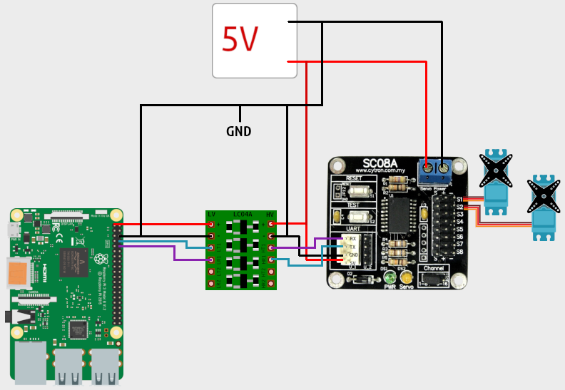
- Connect the RPi to the SC08 servo controller via a logic level converter. We need to do this because the servo controller needs 5V while the RPi provides 3.3V. Also I wouldn’t use the RPi to power anything else than itself.
- Connect the RPi to the L298N driver
You should have connected most parts of the board and motors. But since we’re using a RPi and not an Arduino UNO board, here is what changes:
| L298N PINs | Raspberry Pi physical PINs |
|---|---|
| ENA | 32 |
| IN1 | 38 |
| IN2 | 36 |
| IN3 (IN1 for B channel) | 16 |
| IN4 (IN2 for B channel) | 18 |
| ENB | 12 |
Make sure all grounds are properly connected.
Programming
So we need to create a few libraries to facilitate the re-use of the components. In the links to the C code, don’t forget to also download the .h headers. There is a Makefile provided for your convenience. This need to be built on the chroot environment we created earlier.
- UART
The code to control the UART on the RPi is found here. It’s pretty standard and feel free to find better code. - SC08A
To control this controller via UART, we need to write the proper encoding as described on the user manual. Note this manual is partial (the last pages from the original which might not be available anymore).
This code library does all the required, provided you used the same RPi PINs as above description.
To use the controller in your programs, you need to:
– start the UART (from uart.h)
– enable the channel (from controller.h) usingenableDisableChannel(0,1)
The first argument 0 is to select a single SC08A board. Use a 1 if you cascade 2 boards.
The second argument 1 is to enable that channel. Use 0 to disable it, which you should do before ending the program.
– then use the setAngle method to position the servo. The parameters are:
— the channel, i.e. 1-8 from the S1-S8 pins on the board
— the angle: a value between -90 and 90 as it is expecting a 180 degrees servo
— the speed: a value between 0 and 100. I defaulted to 50.
This is an example program to control the 2 servos for the deadite head. - L298N
Finally we need to control the wheels of the car. This code will provide the default functionalities. Then you can drive the car on a pre-recorded route. Or control it remotely, but you’ll need to program that yourself though. These are client/server examples to get you started.
Result
Closing words
I really enjoyed working on this project. I started with a pre-made build (the YouTube videos shaed above) and upgraded the wheel motors, got rid of the Arduino and wrote all the necessary code to drive from a RPi. It brought me back to my University times.