Remote control toys are all boys favorites. So I wanted to try taking a short trip to my childhood and remote control a simple DC motor from a LEGO helicopter I got as a “Secret Santa” last Christmas.
The result
What you’ll need
These are the components you’ll need:
- 2x Arduino Nano Ever
- 2x 434MHz wireless UART modules (1 as emitter, 1 as receiver)
- 1x Flex Sensor
- 1x 10kΩ Resistor
- 2x 220Ω Resistor
- 1x 270Ω Resistor
- 1x LED (any color)
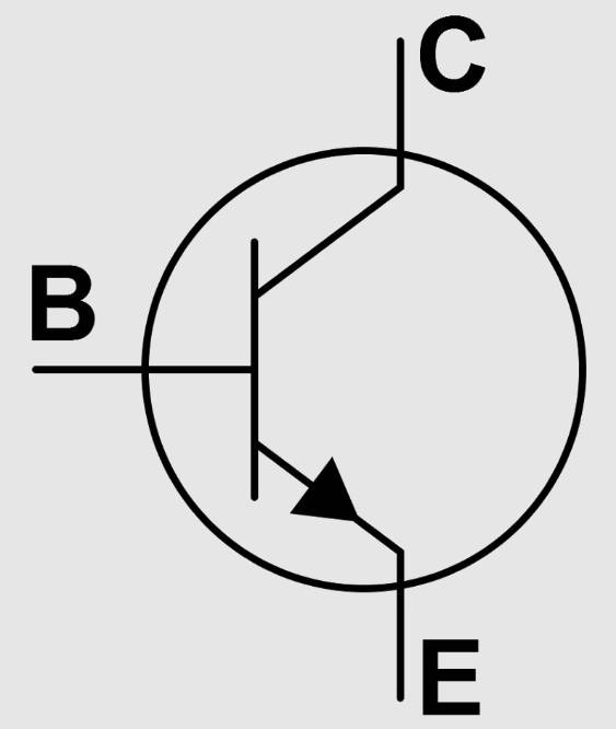
- 1x PN2222 Transistor
- 1x 1N4001 Diode
- 1x DC Motor
- Some cables
- Some small breadboards or strip boards
- Soldering equipment
Motor and receiver
Let’s look at getting the motor running and receiving commands from Arduino Nano Ever. This is the circuit schematic:
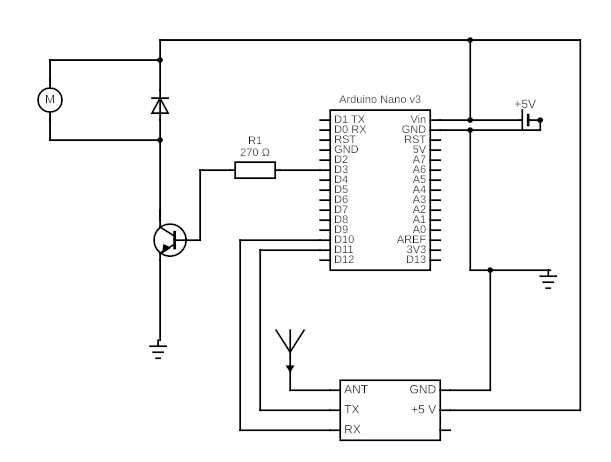
Electronic explanation
Let’s start with the ground on the left of the schema. We have the PN2222 transistor that will let the 5V flow through from the collector to the emitter when the input current from the base if the input voltage between the base and the emitter Vbe is positive.
Note there is usually a drop of 0.7V through the transistor between the base and the emitter so we need Vb – 0.7 > 0 for current to flow. Here Vce is 5V. When the Arduino pin signal is LOW (i.e. 0V) then (0-0.7) is lower than 0 and the current does not flow. As we will see in the program, we will gradually increase (10 steps increase of ~0.5 V) from the Arduino pin. When we reach enough voltage the current will start flowing and running through the motor. Since the transistor has a gain applied to the current Ice from the collector to the emitter, by increasing the Vce voltage we can control the speed of the motor. The 270Ω resistor is here protect the transistor by limiting the base current Ic = Vb/R.
The 1N4001 diode is here to protect the transistor. It is used as a Flyback diode. When the circuit is closed, the motor runs and there is no current in the diode (it is connected opposite to the current). When the circuit is open, as the motor stops there is a large current re-flux pushed back to the transistor. Since the current is inverted, it can flow freely through the diode (path of least resistance compared to going through the transistor) and back to the motor (which might turn slightly in the opposite direction).
Next we connect the 434MHz wireless UART module to 5V and GND, and the TX and RX pins to the RX and TX of the Arduino. Note we have chosen pins D10 and D11 for TX and RX, respectively. If you mix them, either swap the connections or in the code (rxPin, txPin).
Finally power the Arduino on Vin with the 5V supply.
Program
Then the program in Arduino IDE is as follows
#include <SoftwareSerial.h>

#define txPin 10
#define rxPin 11
#define motorPin 3

SoftwareSerial mySerial =  SoftwareSerial(rxPin, txPin);
int availableBytes;

void setup() {
  pinMode(motorPin, OUTPUT);
  pinMode(rxPin, INPUT);
  pinMode(txPin, OUTPUT);
  mySerial.begin(9600);
}

void loop() {
  int speed = readSpeed();
  if (speed >= 0) {
    remoteDebug("Speed: ", speed);
  }
  if ( speed == 0) stop();
  else if (speed > 0) {
    speed = map(speed, 1, 10, 0, 100);
    run(speed);
    remoteDebug("Converted speed: ", speed);
  }
  delay(250);
}

int readSpeed() {
  int speed = -1;
  if (mySerial.available() > 0) {
    int dataRead = mySerial.read();
    if (dataRead > 0 && dataRead != 10 && dataRead != 13) {
      remoteDebug("Raw: ", dataRead);
      if (dataRead == 113) speed = 0;
      else {
        // Read then mod 10 and add 1: range [1,10]
        speed = ((dataRead - 48) % 10) + 1;
        remoteDebug("Converted to: ", speed);
      }
    }
  }
  return speed;
}

void run(int speed) {
  if (speed > 0 && speed <= 255) {
    analogWrite(motorPin, speed);
  }
}

void remoteDebug(String message, int speed) {
  String str = message + "[" + String(speed) + "]";
  int len = str.length() + 1;
  char dataToSend[len];
  str.toCharArray(dataToSend, len);
  mySerial.write(dataToSend);
  mySerial.write("\n");
}

void stop() {
  digitalWrite(motorPin, LOW);
}
Let’s break it down:
We define some constant for the UART and motor pins, we declare the serial device and configure it with the constant we have declared. So far so good.
The setup is just to initialize the pins. In the loop, we will:
– read the speed from the serial port
– if the speed is higher than 0 we debug it (see below)
– if the speed is 0 then we send the stop command
– else we normalize the speed to a 0-100 range to control the motor via the transistor
– we add a delay of 250 ms otherwise we won’t be able to give time to the thread to read from the serial communication and the motor won’t start/stop
The readSpeed function reads from the serial port (in fact the 434MHz receiver). We skip the CR and LF values (10, 13). If the value is 113 (char ‘q’) then we set the returned value, or the speed, to 0. Otherwise we convert the ASCII value to a number between 1-10 and return it.
The run function simply writes the speed to the motor pin output.
Finally the remoteDebug sends data to the serial port. That will allow us to see what is interpreted for debugging if something doesn’t work.
Flex sensor and emitter
On the emitter side, we will use the flex sensor and transmit the resistor value, which varies as the flex is… flexed, to the 434MHz wireless UART module.
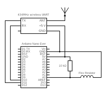
Electronic explanation
This circuit is much simpler. First we connect the Flex sensor between the ground and the analogue A0 pin of the Arduino. The A0 side of the Flex sensor is connected to the 5V pin via a 10k resistor.
As the Flex sensor is bent, its resistance increases, making the input on A0 increase. Think of it as a Voltage divider:

Here, U2 = U x R2 / (R1 + R2) with R1 the 10kΩ resistor and R2 is our Flex sensor. When R2 increases, U2 increases. U2 is the voltage between A0 and GND in our schema.
The Flex sensor has a resistance value of about 10kΩ and 35kΩ. The tension U = 5V. So the value U2 will vary between:
- Low U2 = 5 x 10 / (10+10) = 2.5V
- High U2 = 5 x 35 / (10+35) = 3.9V
The range of the analogue input is 0-1023 (which represent 0 to 5V). By applying the cross multiplication we should be able to determine the boundary values on A0:
- Low: 2.5 * 1023 / 5 = 511
- High: 3.9 * 1023 / 5 = 797
However when connecting the circuit and sending the A0 value to the serial monitor, I found the values moving between 780 and 880. I guess my approximation above is not really accurate 🙂 . So I used these values in the program. I recommend you do the same to have better results.
The other montage is same as previous, to connect the 434MHz wireless UART module to the Arduino.
The program
#include <SoftwareSerial.h>

#define rxPin 10
#define txPin 11
const int flexPin = A0;

SoftwareSerial mySerial =  SoftwareSerial(rxPin, txPin);
String lastValue = "";

void setup() {
  pinMode(flexPin, INPUT);
  pinMode(rxPin, INPUT);
  pinMode(txPin, OUTPUT);
  mySerial.begin(9600);
  Serial.begin(9600);
}

void loop() {
  int speed = readSpeed();
  String value = "q";
  if (speed > 0) {
    value = String(speed);
  }
  sendSpeed(value);
  debug();
  delay(500);
}

int readSpeed() {
  int readValue = analogRead(flexPin);
  if (readValue <= 1) {
    readValue = 0;
  } else {
    // Use your own values there.
    readValue = map(readValue, 780, 880, 0, 9);
  }
  if (readValue > 9) {
    readValue = 9;
  }
  return readValue;
}

void sendSpeed(String str) {
  if (str == lastValue) return;
  lastValue = str;
  int len = str.length() + 1;
  char dataToSend[len];
  str.toCharArray(dataToSend, len);
  mySerial.write(dataToSend);
  mySerial.flush();
  Serial.println("Sent: " + str);
}

void debug() {
  if (mySerial.available() > 0) {
    String str = mySerial.readString();
    Serial.println(str);
  }
}
Once you have connected it all and put the whole circuits in good shape (mine is very prototype looking LOL) you should be able to control the motor remotely.
References
I used these two resources to build this project:
- https://www.instructables.com/How-to-use-a-Flex-Sensor-Arduino-Tutorial/
- https://tutorial.cytron.io/2014/05/15/wireless-uart-arduino-433mhz-434mhz-module/
I purchased the wireless modules, Arduino Nano units and Flex sensor on https://cytron.io